Construction features
Procedure
The basis for the selection of belt type, belt length and the depending pulleys is the surrounding construction. All belt types of our manufacturing range can be equipped with flights/profiles. Timing belts together with bed plates enable a reduced friction transportation. BRECO® and BRECOFLEX® polyurethane timing belts in the version PAZ are available alternative. (PAZ = nylon coating on tooth side).
Selection of the flight
The material to be transported and the transport purpose influence the selection of the flight. Following possibilities of flight versions are available:
Extract of more than 2000 available flight shapes
Flights are manufactured as polyurethane moulded part. From page "profiles of existing mould (extract)", dimensional sheets for profiles of standard version are listed.
Standard profiles/flights can be changed by post-manufacture processes (drilling, milling) depending on dimensions. If necessary, explain design requirements by means of a drawing.
Profiles/Flights of sheet material
Depending on the quantity, flights will possibly be cut from pre-fabricated PUR sheets.
The following board thicknesses are available: 1.5; 2; 3; 4; 5; 6; 7; 8; 10; 11; 15; 20 mm
Profiles/Flights from a new mould
Within the framework of our production possibilities, there are practically no limitations for new design requirements as far as the shape of injection moulded flights are concerned. Tool costs are to be taken into consideration.
Profile material
Polyurethane approx. 92 shore, same material the BRECO®, BRECOFLEX® polyurethane timing belt is made of.
Profile position opposite the tooth
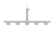
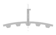
The belt flexibility of timing belts is located mainly in the tooth gap area. To retain the timing belt flexibility around the pulley, the profile position "opposite the tooth" is to be preferred.
Profile pitch, tooth pitch
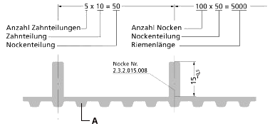
Preferably select a profile pitch which is an integer multiple of the tooth pitch. Profile pitches other than in integer numbers are possible, it must, however, be taken in account that a consistent offset of the profile position in relation to the tooth position will continue in a cumulative way.
Order example
Dimensioning
The equipping of the timing belt with profiles is always made as a multiple of the tooth pitch, i.e. the welded on flight position follows exactly the belt tooth pitch. For this reason, a cumulative error from profile pitch to tooth pitch will not occur.
Tolerances
The reached profile position of each individual profile is ± 0.5 mm of the intended set point position. A tolerance of - 0.5 mm is to be taken into account for the profile height.
Order code, order text
For the required flighted timing belt the order should preferably be accompanied by a dimensional drawing.
The flighted timing belt can also be defined and transmitted by the order text. Example: BRECO® polyurethane timing belt 50 T 10/5000 V-PAZ with welded-on flights, flight no. 2.3.2.015.008, number of flights 100, flight pitch 50, flight position opposite the tooth.
Flash


A flash builds up between flight and back of the belt. A polyurethane overhang with a 0.5 to 1 mm radius could form.
Should the flash impair the intended function, ask for "clean up flash" in your order information.
Profile thickness s
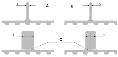
The timing belt flexibility can be influenced by the welded-on flight. Note as a rule that the flight thickness s is to be selected as thin as possible. The table below shows the individually recommended maximum profile thickness in mm in relation to the selected number of pulley teeth.
Max. profile thickness s in mm
20, 25, 30, 40, 50, 60, 100 - Number of teeth of the pulley
A - Maximum profile thickness in mm when profile position opposite the tooth
B - Maximum profile thickness in mm when profile position opposite the tooth gap
| Pitch | 20 | 20 | 25 | 25 | 30 | 30 | 40 | 40 | 50 | 50 | 60 | 60 | 100 | 100 |
| B | B | A | A | B | B | B | ||||||||
| T 5 | 5 | (2) | 6 | (2) | 6 | (3) | 8 | (4) | 9 | (6) | 10 | (8) | 12 | (10) |
| T 10 | 8 | (3) | 9 | (4) | 10 | (4) | 12 | (6) | 14 | (9) | 15 | (12) | 20 | (20) |
| T 20 | 12 | (5) | 13 | (5) | 15 | (6) | 18 | (8) | 20 | (12) | 23 | (20) | 30 | (30) |
| AT 5 | 5 | (2) | 6 | (2) | 6 | (3) | 8 | (4) | 9 | (6) | 10 | (8) | 12 | (10) |
| AT 10* | 8 | (3) | 9 | (4) | 10 | (4) | 12 | (6) | 14 | (9) | 15 | (12) | 20 | (20) |
| AT 20 | 12 | (5) | 13 | (5) | 15 | (6) | 18 | (6) | 20 | (12) | 23 | (20) | 30 | (30) |
| XL | 5 | (2) | 6 | (2) | 6 | (3) | 8 | (4) | 9 | (6) | 10 | (8) | 12 | (10) |
| L | 6 | (3) | 7 | (3) | 8 | (4) | 10 | (5) | 12 | (7) | 13 | (10) | 16 | (16) |
| H | 8 | (4) | 9 | (5) | 10 | (6) | 12 | (7) | 14 | (10) | 15 | (12) | 20 | (20) |
| XH | 13 | (5) | 14 | (5) | 15 | (6) | 18 | (8) | 20 | (12) | 23 | (20) | 30 | (30) |
* suitable as well for BAT and SFAT
Example for the calculation of the profile thickness s for a BRECO® polyurethane timing belt with pitch T 10, which is running around a pulley with 20 teeth:
- When the profile position is "opposite the tooth", profile thickness s = 8 mm,
- When the profile position is "opposite the tooth gap", profile thickness s = 3 mm,
Remark: We recommend to select the next smaller size as profile thickness when there are intermediate sizes (e.g. 22 teeth).
Flights with undercut
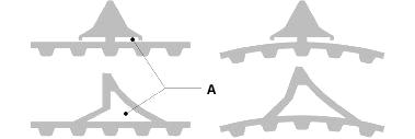
The timing belt flexibility is assured, when there are planned corresponding undercuts.
Profile pair

Profile pairs (flight chambers, flight pockets) are preferred in the transport technology for parts positioning and for so-called lay-up procedures. For the clearance between the profiles, the production tolerance amounts to ± 0.5 mm. Indicate a tolerance reduced to ± 0.2 mm separately, while taking make-ready and/or tool costs into consideration.
Flights with bore holes

It is possible to ask for boreholes for special profile attachments. Tolerances are to be noted.
Profiles with moulded-in inserts
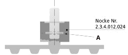
Profiles with moulded-on inserts can be manufactured for special functional characteristics. To shape moulded-in inserts (steel, aluminium or similar) please ensure the existence of appropriate undercuts.
Remark: The orderer has to make available a sufficient number of moulded-in inserts with an approx. 5 % surplus for the manufacture of samples.
Joined version
Joining is made by welding the full profile fitting surface on the back of the belt.
